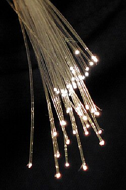
現代のデジタル社会を支える不可欠なインフラである光ファイバーは、ガラスやプラスチックで作られた極めて細い柔軟な繊維です。この技術の最大の特徴は、電気信号ではなく「光」を用いて情報を伝送することにあります。従来の銅線ケーブルと比較して、光ファイバーは圧倒的なデータ転送速度(帯域幅)を誇り、長距離伝送においても信号の劣化が少ないため、世界規模の通信ネットワークの基盤となっています。
また、通信以外にも、医療用の内視鏡(ファイバースコープ)による画像伝送や、特殊な照明、高精度なセンサーなど、光を効率的に導く特性を活かした幅広い分野で活用されています。
Key Facts
- 全反射の原理:屈折率の異なるコアとクラッドの構造により、光を内部に閉じ込めて伝送する。
- 低損失・高帯域:電気ケーブルよりも信号減衰が少なく、電磁干渉(EMI)の影響を全く受けない。
- 2つの主要タイプ:短距離・高出力向けの「マルチモード」と、長距離通信向けの「シングルモード」がある。
- 素材の進化:主にシリカガラスが使われ、製造技術の向上により伝送損失は劇的に減少した。
光ファイバーを支える物理的メカニズム
屈折率と全反射
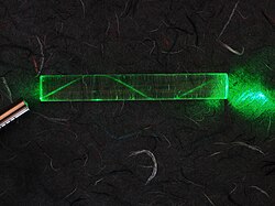
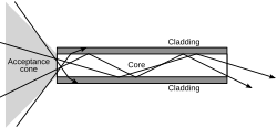
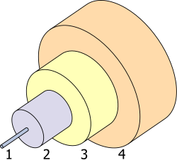
光ファイバーが光を運べる理由は、屈折率(真空中の光速に対する物質中の光速の比)の差を利用した「全反射」という現象にあります。ファイバーの中心部である「コア」を、それよりも屈折率の低い「クラッド」という層が取り囲んでいます。光が特定の角度(臨界角)以上で入射すると、境界線で外に漏れることなく内部に跳ね返り続け、導波路として機能します。
シングルモードとマルチモードの違い
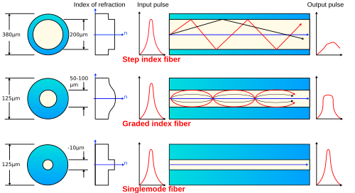
光の伝わり方によって、大きく2つの種類に分けられます。マルチモードファイバーはコア径が太く、複数の光の経路(モード)が存在するため、短距離の通信や高出力の光伝送に適しています。一方、シングルモードファイバー(SMF)はコア径が非常に細く、単一の経路のみで光が伝播します。これにより信号の乱れが抑えられるため、1,050メートルを超えるような長距離通信の主流となっています。
光ファイバーの歴史と技術革新
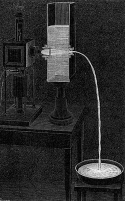
光を曲げて導く原理は、1840年代にダニエル・コラドンとジャック・バビネによって実証されました。その後、ジョン・ティンダルが全反射の特性を詳しく解説し、20世紀初頭には歯科治療などの体内照明に利用されるようになりました。
データ通信への応用は1960年代に加速します。1965年にマンフレート・ボルナーが初のデータ伝送システムを実証し、1968年にはNASAが月面探査のテレビカメラにこの技術を導入しました。その後、コーニング社のトーマス・メンサによる製造速度の劇的な向上(秒速2mから50m以上へ)により、コストが銅線以下となり、世界的な普及が始まりました。
さらに、1980年代後半にはエルビウム添加光ファイバー増幅器(EDFA)が開発され、電気信号に変換して増幅するリピーターを減らすことが可能になったため、超長距離通信のコストが大幅に削減されました。
伝送損失の原因と素材の特性
光がファイバーを通過する際、一部のエネルギーが失われる「減衰(アッテネーション)」が発生します。シリカガラス製ファイバーにおける主な要因は以下の通りです。
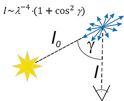
- レイリー散乱:ガラス内部の微細な密度変動により光が散乱する現象。通信波長帯において最大の損失要因となります。
- 赤外吸収:特定の波長以上の光がガラス自体に吸収される現象。
- 不純物吸収:材料に含まれる不純物(水酸基など)による吸収。
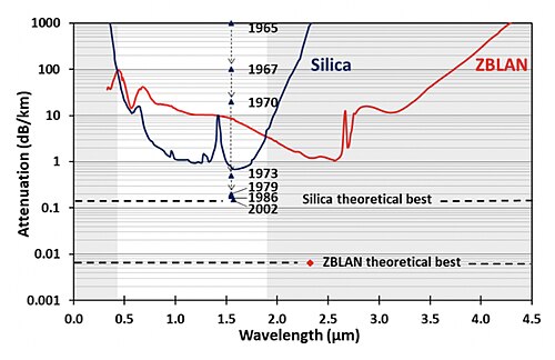
![Experimentally measured spectral attenuation of silica core optical fiber.[74] Minimum attenuation is 0.1400 dB/km at 1560 nm wavelength.](/images/4a/79/4a79bfbef938c81201f0442685b3d6452676a5448edf4929475e98e4c4547756.jpg)
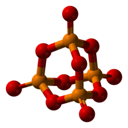
素材としては、汎用性の高いシリカガラスのほか、より低損失を追求したフルオライドガラス(ZBLANなど)や、特殊な用途向けのホスフェートガラス、カルコゲナイドガラスなどが存在します。特にフルオライドガラスは理論上の損失が極めて低いものの、脆く、製造が困難であるという課題があります。
製造プロセスと実用的な構成
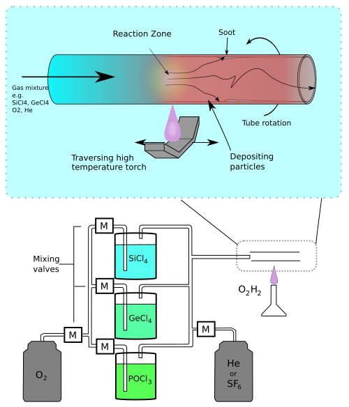
高品質な光ファイバーは、まず「プリフォーム」と呼ばれる太いガラス棒を製造し、それを高温で加熱して引き伸ばす(ドローイング)ことで作られます。化学気相成長法(MCVDなど)を用いて、コアとクラッドの屈折率を精密に制御します。
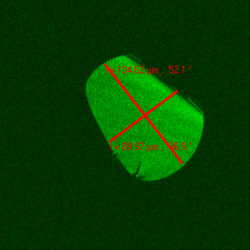
完成したファイバーは非常に細いため、外部からの衝撃や湿気から保護するために、バッファ層やジャケット(被覆)で覆われます。実際の敷設現場では、ファイバー同士を融着接続し、保護エンクロージャに収納して運用されます。
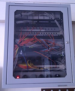
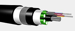
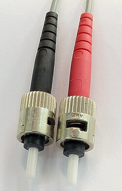
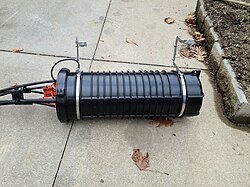
多様な応用事例
光ファイバーの用途は通信だけにとどまりません。以下のような多様な分野で活用されています。
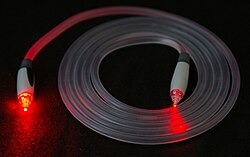
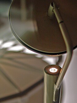
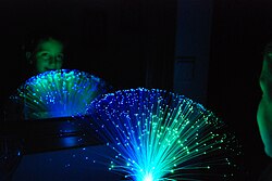
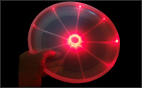
- 照明・採光:太陽光を室内に導くデイライティングや、装飾用ランプ、LEDの光を分散させる照明器具。
- 医療・産業イメージング:狭い空間から画像を取り出すファイバースコープ。
- 軍事・センサー:電磁干渉を受けない特性を活かしたドローン制御や、高精度な環境センサー。
- 電力伝送:光を用いた電力伝送の研究開発。
技術仕様まとめ
| 項目 | シングルモード (SMF) | マルチモード (MMF) |
|---|---|---|
| コア径 | 非常に細い (約8 $\mu$m) | 太い (50 $\mu$m $\sim$ 62.5 $\mu$m) |
| 伝搬モード | 単一 | 複数 |
| 主な用途 | 長距離通信、基幹網 | 短距離通信、LAN、高出力伝送 |
| 伝送距離 | 1,050m以上の長距離に最適 | 短距離向け |
| 信号劣化 | 極めて少ない | モード分散により相対的に多い |
![Dispersion orders of fused silica. GDD: Group delay dispersion, TOD: 3rd-order dispersion, FOD: 4th order, FiOD: 5th order, SiOD: 6th order, SeOD: 7th order, EOD:8th order, NOD: 9th order, TeOD: 10th order[107][108]](/images/3e/ec/3eec54dcafeb8ac681bb6408460ae76e9ca6e8495ce90f84b9ecb3ff5bc8ab40.png)
Frequently Asked Questions
光ファイバーはなぜ電気ケーブルより速いのですか?
光ファイバーは光(電磁波の高周波)を利用するため、電気信号よりもはるかに広い帯域幅を確保でき、一度に大量のデータを送ることができるからです。また、電気的な抵抗による信号の減衰が極めて少ないため、高速な伝送を維持したまま長距離まで届けることが可能です。
「全反射」とは具体的にどのような現象ですか?
光が屈折率の高い媒体(コア)から低い媒体(クラッド)へ向かう際、入射角がある一定の角度(臨界角)を超えると、光が境界線で外に透過せず、すべて内部に反射される現象です。これにより、光はファイバーの内部でジグザグに跳ね返りながら先へと進みます。
シングルモードとマルチモードの使い分けはどう決まりますか?
主に「距離」と「コスト・用途」で決まります。数キロメートル以上の長距離伝送が必要な場合は、信号の乱れが少ないシングルモードが必須です。一方で、ビル内などの短距離で、安価な光源(LEDなど)を使用したい場合や、高い光パワーを伝送したい場合はマルチモードが適しています。
光ファイバーの「損失」とは何のことですか?
光がファイバーの中を進む間に、散乱や吸収によって光の強さが弱くなることを指します。主な原因は、ガラス内部の微細な構造による「レイリー散乱」や、材料に含まれる不純物による吸収です。この損失が少ないほど、リピーター(増幅器)を置かずに遠くまで信号を届けられます。
光ファイバーは切れたらどうなりますか?
光の通り道が遮断されるため、通信は完全に停止します。ただし、物理的に切断された箇所を特定し、「融着接続」という技術でガラス端面を高温で溶かして接合することで、再び低損失な伝送路を復旧させることができます。
References
- Including and .
- This feature is offset by the fiber's susceptibility to the gamma radiation from the weapon. The gamma radiation causes the optical attenuation to increase considerably during the gamma-ray burst due to the darkening of the material, followed by the fiber itself emitting a bright light flash as it anneals. How long the annealing takes and the level of the residual attenuation depends on the fiber material and its temperature. See
- The fiber, in this case, will probably travel a longer route, and there will be additional delays due to communication equipment switching and the process of encoding and decoding the voice onto the fiber.
- The electromagnetic analysis may also be required to understand behaviors such as speckle that occur when light propagates in multi-mode fiber.
- The behavior of larger-core multi-mode fiber can also be modeled using the wave equation, which shows that such fiber supports more than one mode of propagation (hence the name). The results of such modeling of multi-mode fiber approximately agree with the predictions of geometric optics, if the fiber core is large enough to support more than a few modes.
- For applications requiring spectral wavelengths, especially in the mid-infrared wavelengths (~ 2–7 μm), a better alternative is represented by such as and InF3.
📸 フォトギャラリー