Figure 1. The light path through a Michelson interferometer. The two light rays with a common source combine at the half-silvered mirror to reach the detector. They may either interfere constructively (strengthening in intensity) if their light waves arrive in phase, or interfere destructively (weakening in intensity) if they arrive out of phase, depending on the exact distances between the three mirrors.
← ホームへ戻る
干渉法インターフェロメトリマイケルソン干渉計光学的測定波面分割

干渉法(インターフェロメトリ)の原理と多角的な応用展開

🗓 2026年8月10日

干渉法(インターフェロメトリ)とは、重なり合った波の干渉現象を利用して、極めて微細な情報を抽出する高度な計測技術です。主に電磁波(特に光)が用いられ、ナノメートル単位の精度で距離や形状を測定できるため、現代の科学計測において最高精度の長さ測定手段として位置づけられています。

この技術は、天文学から量子力学、生物医学、工業的な表面粗さ測定まで、驚くほど幅広い分野で活用されています。基本的には、単一の光源から出た光を2つの経路に分け、再び合流させた際に生じる「干渉縞」を解析することで、光路差や屈折率の変化、表面の不規則性を導き出します。

Key Facts

  • 超高精度計測: ナノメートル精度の長さ測定が可能であり、現存する最高精度の計測手法の一つである。
  • 干渉縞の活用: 2つの光路の差が干渉縞として現れ、これを解析して形状や距離を特定する。
  • 広範な応用: 天文学の解像度向上から、半導体産業の膜厚測定、医療用OCT(光干渉断層撮影)まで利用される。
  • 多様な方式: 波面分割型や振幅分割型など、目的に応じて異なる干渉計の構成が使い分けられている。

干渉計の基本メカニズムと動作原理

多くの干渉計では、1つの光源から分かれた2つのビームが異なる経路を通り、再び結合されることで干渉が起こります。このとき、波の位相が揃っていれば強め合い(強め合う干渉)、逆位相であれば弱め合います(弱め合う干渉)。この結果として現れる明暗のパターンが「干渉縞」です。

例えば、代表的なマイケルソン干渉計では、ハーフミラー(半透鏡)を用いて光を2方向に分け、それぞれのミラーで反射させて戻します。ミラー間の距離がわずかに変化するだけで干渉縞が変動するため、極めて微小な変位を検出できます。
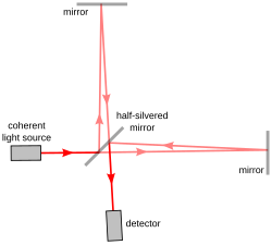
Figure 1. The light path through a Michelson interferometer. The two light rays with a common source combine at the half-silvered mirror to reach the detector. They may either interfere constructively (strengthening in intensity) if their light waves arrive in phase, or interfere destructively (weakening in intensity) if they arrive out of phase, depending on the exact distances between the three mirrors.

干渉縞の形状は、光学素子の配置や光源の性質によって変化します。ミラーが互いに垂直に配置されている場合は同心円状の縞が現れますが、ミラーをわずかに傾けると双曲線などの円錐曲線状になり、さらに条件が揃えば平行な直線状の縞が得られます。
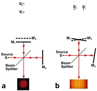
Figure 2. Formation of fringes in a Michelson interferometer

また、使用する光の種類によっても縞の特性は異なります。単色光(ナトリウムD線など)を用いると明確な縞が得られますが、白色光を用いると位相反転の回数に応じて異なる色の縞が現れます。
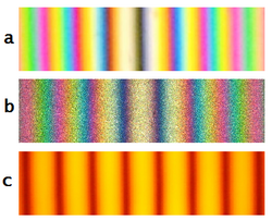
Figure 3. Colored and monochromatic fringes in a Michelson interferometer: (a) White light fringes where the two beams differ in the number of phase inversions; (b) White light fringes where the two beams have experienced the same number of phase inversions; (c) Fringe pattern using monochromatic light (sodium D lines)

干渉計の分類と構造的アプローチ

干渉計は、光をどのように分割し、どのように検出するかによっていくつかのカテゴリーに分類されます。

光分割の手法による分類

  • 波面分割型(Wavefront Splitting): 光の波面を物理的に分割して干渉させる方式です。
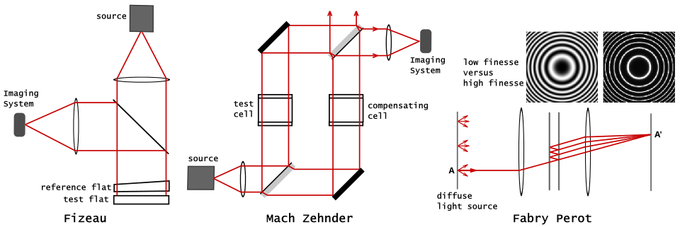
  • 振幅分割型(Amplitude Splitting): 光の振幅(強度)を分けて異なる経路を通す方式で、マイケルソン、マッハ・ツェンダー、ファブリ・ペローなどがこれに該当します。
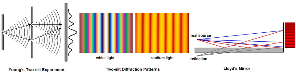
Figure 5. Two wavefront splitting interferometers
Figure 6. Three amplitude-splitting interferometers: Fizeau, Mach–Zehnder, and Fabry Pérot.

経路構成による分類

  • ダブルパス(Double Path): 2つの独立した光路を持つ構成です。
  • コモンパス(Common Path): 2つのビームがほぼ同じ経路を共有する構成で、外部振動などのノイズに強い特性があります。
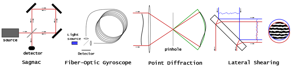
Figure 4. Four examples of common-path interferometers

科学・産業における具体的な応用事例

物理学と天文学への貢献

物理学における金字塔的な事例に、マイケルソン・モーリーの実験があります。これはエーテルの存在を検証しようとした実験でしたが、結果的に特殊相対性理論の根拠となる重要な知見をもたらしました。現代では、極低温の光学共振器を用いたヘテロダイン測定により、光速の等方性がさらに高精度に検証されています。

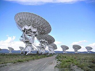
天文学では、複数の電波望遠鏡を組み合わせた干渉計が利用されています。これにより、個々のアンテナの直径ではなく、アンテナ間の最大離隔距離に相当する巨大な単一望遠鏡と同等の解像度を実現しています。
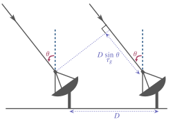
Interferometry is used in radio astronomy, with timing offsets of: D sin θ
Figure 11. The VLA interferometer
ALMA is an astronomical interferometer located in Chajnantor Plateau[45]

エンジニアリングと精密計測

光学部品の検査には、ツイマン・グリーン干渉計が広く用いられています。これはマイケルソン干渉計の派生形であり、コリメーターと単色点光源を用いることで、レンズなどの光学素子の精度を検証します。かつてはコヒーレンス長の制限が課題でしたが、レーザー光源の登場により実用性が飛躍的に向上しました。
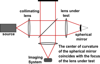
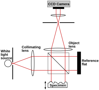
Figure 14. Twyman–Green Interferometer
Figure 19. Twyman–Green interferometer set up as a white light scanner

また、フィゾー干渉計では、コンピュータ生成ホログラム(CGH)を併用することで、非球面ミラーなどの複雑な形状の測定が行われています。
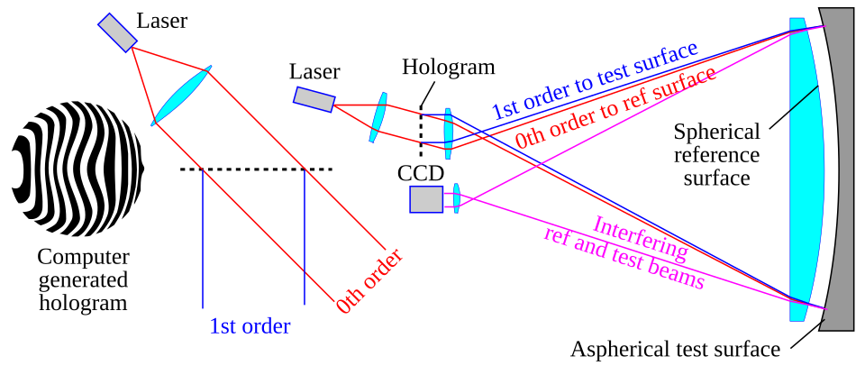
Figure 15. Optical testing with a Fizeau interferometer and a computer generated hologram

さらに、光学フラットを用いた干渉法では、参照面と測定面の隙間に生じる干渉縞を観察することで、表面の平坦度を判定します。平行な直線縞が現れれば平坦であり、縞が歪んでいれば表面に曲率があることを示します。
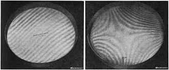
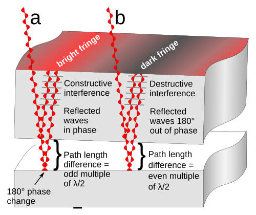
Figure 13. Optical flat interference fringes. (left) a flat surface, indicated by a pattern of straight parallel interference fringes at equal intervals; (right) curved surface.
How interference fringes are formed by an optical flat resting on a reflective surface. The gap between the surfaces and the wavelength of the light waves are greatly exaggerated.

高度な表面解析:コヒーレンス走査干渉法(CSI)

CSIは、光のコヒーレンス時間(干渉が起こる時間的な幅)を利用した手法です。位相ではなく「干渉縞のコントラスト」を監視し、サンプルを垂直方向に走査することで、2πの曖昧さ(位相の周期性による誤認)を排除した3D表面プロファイリングを可能にします。これにより、半導体業界での膜厚測定や、微細な溝・穴の形状測定に活用されています。
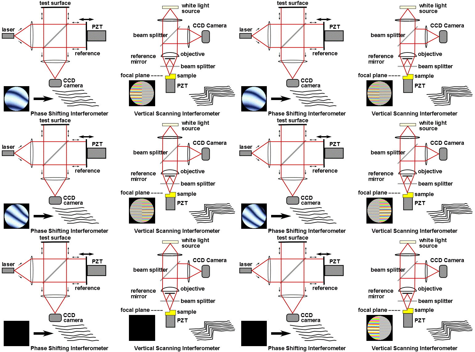
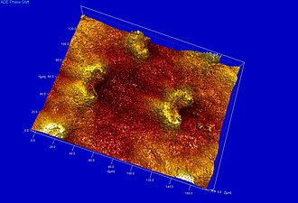
Figure 17. Phase shifting and Coherence scanning interferometers
Figure 18. Lunate cells of Nepenthes khasiana visualized by Scanning White Light Interferometry (SWLI)

その他の先端技術

モード同期レーザーを用いた「周波数コム」は、未知の光学周波数を極めて正確に測定するための基準として機能します。
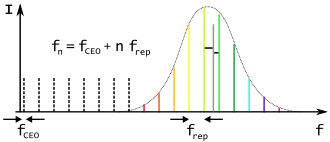
Figure 16. Frequency comb of a mode-locked laser. The dashed lines represent an extrapolation of the mode frequencies towards the frequency of the carrier–envelope offset (CEO). The vertical grey line represents an unknown optical frequency. The horizontal black lines indicate the two lowest beat frequency measurements.

干渉法の概要まとめ

干渉法の主要方式と特徴
方式/名称 主な特徴 主な用途
マイケルソン型 振幅分割・ダブルパス 光速測定、基礎物理実験
ツイマン・グリーン型 コリメート光を利用 光学レンズ・部品の精度検査
CSI(コヒーレンス走査) コントラスト監視・垂直走査 3D表面粗さ、膜厚測定
天文学的干渉計 複数アンテナの信号相関 高解像度の天体観測
フィゾー型 参照面との干渉 非球面などの光学面測定

Frequently Asked Questions

干渉法で測定できる最小単位はどのくらいですか?

使用する光源の波長に依存しますが、一般的にナノメートル(10億分の1メートル)単位の精度で測定可能です。これにより、原子レベルに近い微小な変位や表面の凹凸を検出できます。

「波面分割」と「振幅分割」の違いは何ですか?

波面分割は、1つの波面を物理的に切り分けて干渉させる方法です。一方、振幅分割は、ビームスプリッターなどで光の強度(振幅)を2つに分け、それぞれを異なる経路に通した後に再結合させる方法です。

コヒーレンス走査干渉法(CSI)のメリットは何ですか?

従来のコヒーレント干渉法で問題となる「2πの曖昧さ(位相が1周期回ると区別がつかなくなる現象)」を回避できる点です。これにより、段差のある表面や粗い表面でも正確な3Dプロファイリングが可能です。

天文学で干渉法を使うとどのような利点がありますか?

物理的に巨大な単一の望遠鏡を建設しなくても、離れた場所にある複数のアンテナを同期させることで、それらの最大距離に相当する口径を持つ望遠鏡と同等の高い角分解能を得ることができます。

白色光干渉法と単色光干渉法の違いは?

単色光(レーザーなど)はコヒーレンス長が長く、広い範囲で干渉縞が現れます。対して白色光はコヒーレンス長が非常に短いため、光路差がほぼゼロの地点付近にのみ干渉縞が現れます。この特性を利用して、極めてピンポイントな位置特定や表面測定が行われます。

References

  1. Bunch, Bryan H; Hellemans, Alexander (April 2004). The History of Science and Technology. Houghton Mifflin Harcourt. p. 695.  .
  2. Hariharan, P. (2007). Basics of Interferometry. Elsevier Inc.  .
  3. Patel, R.; Achamfuo-Yeboah, S.; Light R.; Clark M. (2014). "Widefield two laser interferometry". Optics Express. 22 (22): 27094–27101. :2014OExpr..2227094P. :10.1364/OE.22.027094.  25401860.
  4. T.Young, "The Bakerian Lecture:Experiments and Calculations Relative to Physical Optics," Philosophical Transactions of the Royal Society of London 94 (1804): 1–16.
  5. Kipnis, Nahum (1991). History of the Principle of Interference of Light. :10.1007/978-3-0348-8652-9.  .
  6. J. Lequeux, François Arago A 19th Century French Humanist and Pioneer in Astrophysics (Springer International Publishing: Imprint: Springer, 2015).
  7. (2023). Interference: The History of Optical Interferometry and the Scientists Who Tamed Light (Oxford University Press, 2023). Oxford University Press.  .pp. 99-108
  8. Nolte, Interference, pg. 111
  9. Paschotta, Rüdiger (24 October 2009). "Optical Heterodyne Detection". RP Photonics Encyclopedia. RP Photonics Consulting GmbH. :10.61835/79k. Retrieved 1 April 2012.
  10. Poole, Ian. "The superhet or superheterodyne radio receiver". Radio-Electronics.com. Retrieved 22 June 2012.

📸 フォトギャラリー

Figure 1. The light path through a Michelson interferometer. The two light rays with a common source combine at the half-silvered mirror to reach the detector. They may either interfere constructively (strengthening in intensity) if their light waves arrive in phase, or interfere destructively (weakening in intensity) if they arrive out of phase, depending on the exact distances between the three mirrors.
Figure 2. Formation of fringes in a Michelson interferometer
Figure 3. Colored and monochromatic fringes in a Michelson interferometer: (a) White light fringes where the two beams differ in the number of phase inversions; (b) White light fringes where the two beams have experienced the same number of phase inversions; (c) Fringe pattern using monochromatic light (sodium D lines)
Figure 4. Four examples of common-path interferometers
Figure 5. Two wavefront splitting interferometers
Figure 6. Three amplitude-splitting interferometers: Fizeau, Mach–Zehnder, and Fabry Pérot.
Interferometry is used in radio astronomy, with timing offsets of: D sin θ
Figure 11. The VLA interferometer
ALMA is an astronomical interferometer located in Chajnantor Plateau[45]
Figure 13. Optical flat interference fringes. (left) a flat surface, indicated by a pattern of straight parallel interference fringes at equal intervals; (right) curved surface.
How interference fringes are formed by an optical flat resting on a reflective surface. The gap between the surfaces and the wavelength of the light waves are greatly exaggerated.
Figure 14. Twyman–Green Interferometer
Figure 15. Optical testing with a Fizeau interferometer and a computer generated hologram
Figure 16. Frequency comb of a mode-locked laser. The dashed lines represent an extrapolation of the mode frequencies towards the frequency of the carrier–envelope offset (CEO). The vertical grey line represents an unknown optical frequency. The horizontal black lines indicate the two lowest beat frequency measurements.
Figure 17. Phase shifting and Coherence scanning interferometers
Figure 18. Lunate cells of Nepenthes khasiana visualized by Scanning White Light Interferometry (SWLI)
Figure 19. Twyman–Green interferometer set up as a white light scanner